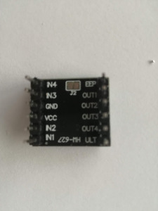
Quite some time ago I bought some cheap DRV8833 Motor Controller Boards (HW-627) from China and now I planned to use them in one of my projects. I was struggling quite a bit to figure out how this is working. This board is using the DRV8833 chip and can control 2 motors in parallel.
Specifications:
- Product size: 18.5*16mm/0.73*0.63″
- Input voltage: 3-10V Single H bridge
- Output current: 1.5A, can drive 2 DC geared motors
- Uses: It can drive DC motors up to 1.5A and 4-wire stepper motors
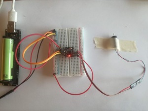
Fist, to test a motor, I connected it directly to the power lines and this was working!
Then I connected VCC and In1 to the power line (+), GND and in2 to ground (-) and the motor to out1 and out2 and to my surprise the LED was on but the motor was not working. It took me quite some time to figure out that EEP must be set to high as well and after connecting it to the power (+) the motor started to spin!
To use the full functionality in Arduino (e.g. with an ESP32, ESP8266 or any other board) use the following:
- VCC: VIN
- GND: GND
- IN1:: general-purpose input/output (GPIO) Pin e.g. D0
- IN2: general-purpose input/output (GPIO) Pin, e.g. D1
- EEP: general-purpose input/output (GPIO) PIN e.g. D3
Define GPIO pins as output and set
- IN1 to high
- IN2 to low
- EEP to high
To reverse the direction
- IN1 to low
- IN2 to high
- EEP to high
It is even better to power the motor from it’s own battery with:
- VCC: Battery +
- GND: Battery – & GND (make sure that the battery and the Microcontroller share a common Ground!)
- IN1:: general-purpose input/output (GPIO) Pin e.g. D0
- IN2: general-purpose input/output (GPIO) Pin, e.g. D1
- EEP: general-purpose input/output (GPIO) PIN e.g. D3
To control the speed – instead of setting the value to high- use analogWrite to set a value to IN1 or IN2.
Power Consumption
For my tests I was using the Racerstar 8520 8.5x20mm 53500RPM Coreless Motor:
The measured power consumption at 5.0V was 0.4 Amps.
5 Comments
Stef · 24. March 2022 at 23:13
be very cautious with this module as it is very fragile! I burnt one while testing on the breadboard, it was so fast I don’t even know what caused it, maybe IN1 and IN2 both on high…
Alex · 12. January 2021 at 21:42
This helped my a lot, especially your hint on EEP. Is the following a mistake?
Define GPIO pins as output and set
IN1 to high
IN2 to low
EEP to high
To reverse the direction
IN1 to high
IN2 to low
EEP to high
Seems to me the same. My guess is to set IN1 to low, IN2 to high, for reverse…
pschatzmann · 13. January 2021 at 12:36
Thanks for your highlighting this mistake!
Alex · 18. January 2021 at 14:13
Thanks for your answer :–) Since I couldn’t find much on this driver on the net, let me share my experiences: I got 5 of them for 2$ total on Aliexpress. Compared to the ubiquitously used L293 series, these drivers are supposed to be more energy efficient and only require two control pins per motor. Unfortunately they hardly survived my poor soldering skills: after soldering, only one of them was still fully working, while the rest had anything from 1-3 canals working. My next move will be to try the TB6612B driver, a bit more expensive bur supposedly even more energy efficient (and hopefully able to survive my soldering).
pschatzmann · 31. January 2021 at 12:56
How funny – I had the same problems with my soldering 🙂