In the last Blogs I presented a File Based Versatile MP3 Player and later a A Versatile but Simple Arduino Streaming MP3 Player using my Arduino Audio Tools Library.
In this Blog, I will demonstrate how easy it is to convert it into a AAC player. I also show how to control the volume.
So far I was usually using an ESP32 to test the sketch. This time I switch to the cheaper ESP8266!
The Sketch
Here is the Arduino Sketch:
#include "AudioTools.h"
#include "AudioCodecs/CodecAACHelix.h"

using namespace audio_tools;

const char *urls[] = {
  "http://relay.publicdomainradio.org/jazz_swing.aac",
  "http://stream.srg-ssr.ch/m/couleur3/aacp_96",
  "http://live9.avf.ch:8000/ipmusicaacplus96"
};
const char *wifi = "wifi";
const char *password = "password";

URLStream urlStream(wifi, password);
AudioSourceURL source(urlStream, urls,"audio/aac");
I2SStream i2s;
AACDecoderHelix decoder;
AudioPlayer player(source, i2s, decoder);
const int volumePin = A0;

void setup() {
  Serial.begin(115200);
  AudioLogger::instance().begin(Serial, AudioLogger::Info);

  // setup output
  auto cfg = i2s.defaultConfig(TX_MODE);
  i2s.begin(cfg);

  // setup player
  player.begin();
}

void updateVolume() {
  // Reading potentiometer value
  float vol = static_cast<float>(analogRead(volumePin));
  // min in 0 - max is 1.0
  player.setVolume(vol/1023.0); // or change for ESP32: 4095.0);
}

void loop() {
  updateVolume();
  player.copy();
}
In order to convert the MP3 code to support AAC, I just needed to replace the urls to provide AAC streams, replace the MP3DecoderHelix with AACDecoderHelix and change the mime to “audio/aac”.
In order to support the volume control, we read an analog Pin (e.g. GPIO15) and call the player.setVolume() method with a value that is in the rage between 0 and 1.0 and we just need to connect a Potentiometer to this pin.
Finally I removed the meta data logic, because this is not needed…
The External DAC
For my tests I am using the 24-bit PCM5102 PCM5102A Stereo DAC Digital-to-analog Converter PLL Voice Module pHAT
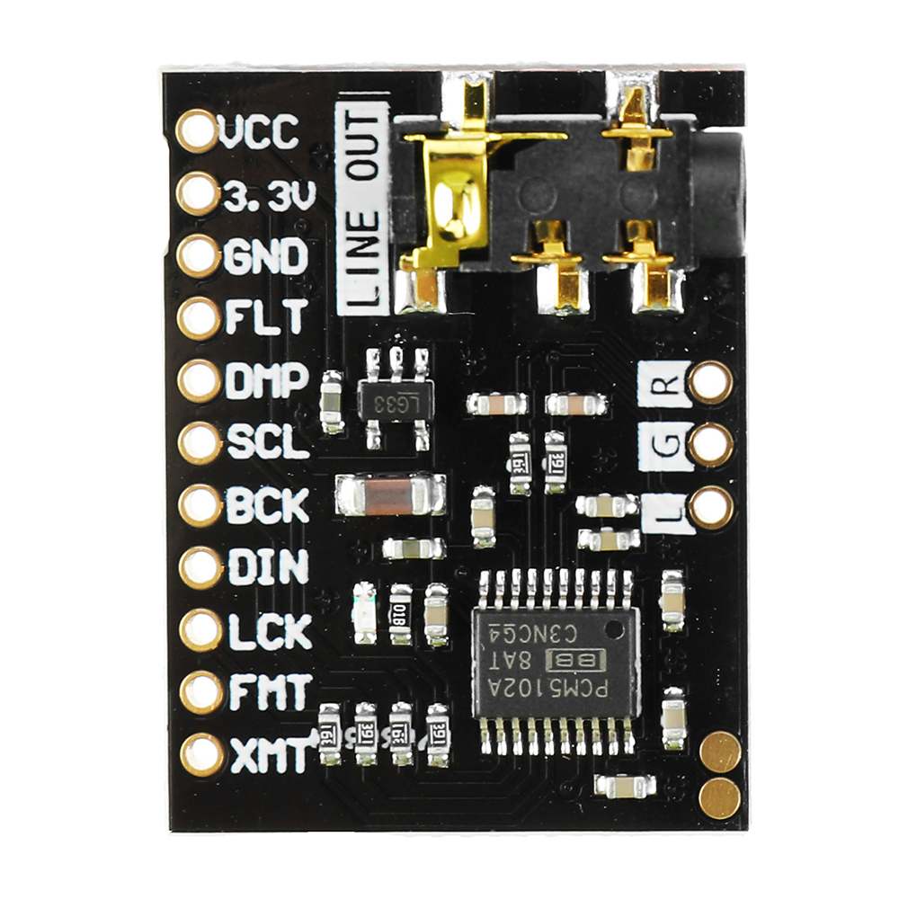
I am just using the default pins defined by the framework. However I could change them with the help of the config object. The mute pin can be defined in the constructor of the I2SStream – by not defining anything we use the default which is GPIO23
| DAC | ESP32 | ESP8266 |
|---|---|---|
| VDD | 5V | 5V |
| GND | GND | GND |
| SD | OUT (GPIO22) | GPIO3/RX0 |
| L/R | GND | GND |
| WS | WS (GPIO15) | GPIO2/TX1 |
| SCK | BCK (GPIO14) | GPIO15 |
| FMT | GND | GND |
| XSMT | +3V | +3V |
- DEMP – De-emphasis control for 44.1kHz sampling rate(1): Off (Low) / On (High)
- FLT – Filter select : Normal latency (Low) / Low latency (High)
- SCK – System clock input (probably SCL on your board).
- FMT – Audio format selection : I2S (Low) / Left justified (High)
- XSMT – Soft mute control(1): Soft mute (Low) / soft un-mute (High)
Wiring the Potentiometer
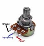
| Pot | ESP32 | ESP8266 |
|---|---|---|
| POW | 3V | 3V |
| GND | GND | GND |
| VOUT | A0/GPIO36 | A0 |
Dependencies
The sketch is using the following dependencies:
Hardware Requirements
- A Microcontroller that supports the Arduino WiFi library (e.g. ESP32, ESP8266…)
- A potentiometer
- An I2S Stereo DAC

0 Comments