Together with Pulseview, the Raspberry Pico can be turned into a Logic Analyzer.
I demonstrated how to build a simple SUMP logic analyzer with my Arduino logic-analyzer library in my last blogs.
In this Blog, I demonstrate how to use the PIO which allows much higher capturing speeds. In theory you we might capture up to 125 MHz. This is well above the 2.5 MHz which is achievable with a regular CPU based approach.
Arduino Sketch
Here is a the Arduino Sketch which uses the PIO:
#include "Arduino.h"
#include "capture_raspberry_pico.h"
using namespace logic_analyzer;

int pinStart=START_PIN;
int numberOfPins=PIN_COUNT;
LogicAnalyzer logicAnalyzer;
PicoCapturePIO capture;

// Use Event handler to cancel capturing
void onEvent(Event event) {
    if (event == STATUS) {
        switch (logicAnalyzer.status()) {
            case ARMED:
                digitalWrite(LED_BUILTIN, LOW);
                break;
            case STOPPED:
                capture.cancel();
                digitalWrite(LED_BUILTIN, LOW);
                break;
        }
    }
}

/// Generates a test PWM signal
void activateTestSignal(int testPin, float dutyCyclePercent) {
    log("Starting PWM test signal with duty %f %", dutyCyclePercent);
    pinMode(testPin, OUTPUT);
    int value = dutyCyclePercent / 100.0 * 255.0;
    analogWrite(testPin, value);
}

void setup() {
    Serial.begin(SERIAL_SPEED);
    Serial.setTimeout(SERIAL_TIMEOUT);
    pinMode(LED_BUILTIN, OUTPUT);

    // generate test signal
    activateTestSignal(pinStart, 90.0);

    logicAnalyzer.setDescription("Raspberry-Pico-PIO");
    logicAnalyzer.setEventHandler(&onEvent);
    logicAnalyzer.begin(Serial, &capture, MAX_CAPTURE_SIZE, pinStart, numberOfPins);
}

void loop() {
    if (Serial) logicAnalyzer.processCommand();
}
The big change to the original Sketch is, that we replace the generic Capture class with the PicoCapturePIO. We also register an event handler, that activates the LED when the capturing is in progress.
The line activateTestSignal(pinStart, 90.0); is used for testing and it generates a test PWM signal with a 90% duty cycle on the first pin.
You can find the example in the examples directory. To build it just execute:
mkdir build
cd build
cmake ..
make
Pulseview
After you have deployed the Sketch you can use it in Pulseview.
Start Pulseview
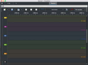
Click on the Device button and fill out the form:
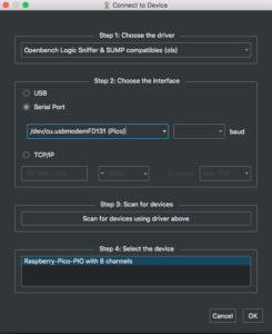
Finally Confirm with OK
To start the capturing, select the frequency and the sample size and click on the Run button:
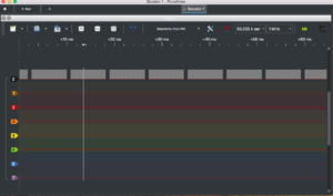
And you can see the PWM test impulse on pin 0!
I hope I could demonstrate how easy it is to develop a dedicated custom Arduino based Logic Analyzer for your preferred processor…
Final Remarks:
The current PicoCapturePIO class does not implement any trigger support and this is currently not a priority for me. So if you have some spare time, any help will be appreciated!


2 Comments
dan · 19. August 2021 at 7:56
Hey this project seems super cool but I cant find the device in pulseview any idea where I went wrong?
pschatzmann · 19. August 2021 at 9:40
Difficult to say:
– I assume you build the sketch as described and deployed it by copying the logic-analyzer-pico-pio.uf2 to the Pico Drive.
– If you use linux or os/x you can double check with ls if you can see the device /dev/tty.usbmodemFA141
– I was double checking with the official Arduino implementation and I can confirm that this is not working.
– This sketch is working however with the Arduino implementation from earlephilhower so you could use the Arduino IDE
– One last thing to make sure is that you do not have any terminal open which is using the /dev/tty.usbmodemFA141 port. If you use the Arduino IDE close it before you connect the device again.
– And do not forget to change the Driver: Pulseview automatically proposes the first one (which is ASIX SIGMA). You need to select “Openbechch Logic Sniffer & SUMP compatible” as shown in the Blog.
Greetings from Switzerland
Phil