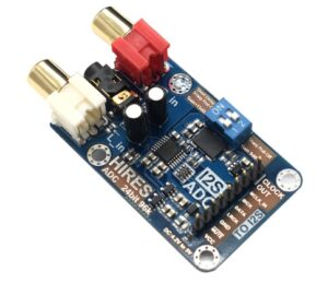
Quite some time ago I have purchased an Audio Analog to Digital Converter (ADC) module, but I never managed to have it working properly. Unfortunately Google Search could not help either and I was the only one using this module or having problems.
The Software
Finally I have it working now and therefore document my setup in the hope that this might save you some time. Since I am doing all my audio projects with my Arduino Audio Tools Library, I first show how to use it there:
    I2SStream i2sStream; // Access I2S as stream
    auto cfg = i2sStream.defaultConfig(RX_MODE);
    cfg.bits_per_sample = 32;
    cfg.channels = 2;
    cfg.sample_rate = 96000;
    cfg.is_master = false;
    cfg.i2s_format = I2S_MSB_FORMAT;
    cfg.use_apll = true;
    i2sStream.begin(cfg);
The key to success was to use it in slave mode with a sampling rate of 96000 and of 32 bits per sample. The noise finally disappeared when I activated the APLL!
The code above roughly translates to the following ESP32 ADF I2S settings:
    i2s_config_t i2s_config = {
            .mode = I2S_MODE_SLAVE | I2S_MODE_RX,
            .sample_rate = 96000,
            .bits_per_sample = (i2s_bits_per_sample_t) 32,
            .channel_format = I2S_CHANNEL_FMT_RIGHT_LEFT,
            .communication_format = I2S_COMM_FORMAT_STAND_I2S,
            .intr_alloc_flags = ESP_INTR_FLAG_LEVEL1, // default interrupt priority
            .dma_buf_count = 8,
            .dma_buf_len = 64,
            .use_apll = true,
            .tx_desc_auto_clear = true // avoiding noise in case of data unavailability
      };
The Hardware Connections
On the ESP32 the I2S pins are defined in the i2s_pin_config_t structure.
| Module | ESP32 |
|---|---|
| BLCK | bck_io_num (e.g. GPIO14) |
| DATA | data_in_num (e.g. GPIO32) |
| LRCK | ws_io_num (e.g.GPIO15) |
| GND | GND |
| MUTE | – |
| VCC | 5V |
Please note that the jumper on the module must be set, so that CLOCK OUT is connecting the MCLK IN pin!
The MUTE pin is pulled high, so it can be floating to produce any output. If you want to control it via a GPIO pin: setting the value to high produces output – low stops output.
As audio input I was connecting an Apple IPAD to the Audio IN of the ADC module.
The Result
Here is the result from the Arduino Plotter:
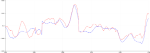
This looks just perfect!
Unfortunately I did not manage to have this working in master mode: I tried to provide the master frequency with the help of the apll
- by setting the sample_rate to 32000 and the fixed_mclk to 8192000
- Connecting the ESP32 VP pin to the MCLCK IN pin of the ADC
- Setting the cfg.is_master to true which leads to .mode = I2S_MODE_MASTER | I2S_MODE_RX,
I got these values from the data sheet of the ADC chip, but that did not work.
So if you find out how to have “Master Mode” working please let me know!
ps. I finally managed to have “Master Mode” working: Details can be found here.

11 Comments
kjms0001 · 5. July 2024 at 22:11
Hello,
I have my module wired with the same pins you chose and my ESP32 is in master mode. I have the MCLK tied to RX0 as well but when i save the file for playback, the recordings are empty. Any help would be appreciated
#define I2S_WS 15
#define I2S_SD 32
#define I2S_SCK 14
void i2s_install() {
// Set up I2S Processor configuration
const i2s_config_t i2s_config = {
.mode = i2s_mode_t(I2S_MODE_MASTER | I2S_MODE_RX),
.sample_rate = 44100, //sampling rate
.bits_per_sample = i2s_bits_per_sample_t(16), //bits per sample (Q: why are we using 16 bits when the capacity is 32 ?)
.channel_format = I2S_CHANNEL_FMT_RIGHT_LEFT, //channel configuration
.communication_format = i2s_comm_format_t(I2S_COMM_FORMAT_STAND_I2S),
.intr_alloc_flags = ESP_INTR_FLAG_LEVEL1,
.dma_buf_count = 8, //Q: Why this value ?
.dma_buf_len = bufferLen, //buffer length: 256 bits
.use_apll = true,
.tx_desc_auto_clear = true
};
i2s_driver_install(I2S_PORT, &i2s_config, 0, NULL);
}
void i2s_setpin() {
// Set I2S pin configuration
const i2s_pin_config_t pin_config = {
.bck_io_num = I2S_SCK,
.ws_io_num = I2S_WS,
.data_out_num = -1,
.data_in_num = I2S_SD
};
i2s_set_pin(I2S_PORT, &pin_config);
}
pschatzmann · 5. July 2024 at 22:18
Why don’t you just follow the documentation ? https://github.com/pschatzmann/arduino-audio-tools/wiki/External-ADC
Volodymyr · 5. January 2023 at 15:26
Hi, Phil!
Is it possible to connect 2 these Audio Analog to Digital Converter (ADC) module, to 1 ESP32?
This could make it possible to get 4 audio channels on one ESP32
Thsnks!
pschatzmann · 9. January 2023 at 21:22
ADC via I2S is only possible on one port. So the answer is no.
You can try to use the available ADCs with together with a Timer – but then the sample rate will be quite limited.
Lukesan · 11. October 2022 at 22:48
Hi Phil, have yet to try things out but would it be possible to use this with Karadio32. I understand there is an issue with using wifi and BT together one 1 ESP32. What if 1 ESP32 serves as a Wifi client, using Karadio32, which sends I2S to another ESP32 which is being used as a BT transmitter? Would that work out? It would make a great low power streaming receiver that can send to BT speakers.
pschatzmann · 12. October 2022 at 11:06
I suggest that you give it a try. I had quite some users that did not manage to get a stable I2S working…
Bill Warren · 20. September 2022 at 18:56
Phil,
It appears that the link for “Master Mode” working details referenced in your article is a dead link.
Can you provide a location for the “Master Mode” working details?
pschatzmann · 25. September 2022 at 10:59
The link has been updated!
jisv48 · 26. April 2022 at 23:09
Hello Phil,
First of all, thank you for your wonderful teaching, tutorials, examples and libraries. I’m trying to use a I2S MEMS ICS43434 mic and a AMP MAX98357A on a esp32 dev kit using your audio tools streams i2s to i2s. But I’m having some trouble configuring the two boards using the example provided. I installed the board using different pins as you have on the default configuration; here are my pins:
For Mic Mems I used:
config.pin_ws = 22;
config.pin_bck = 26;
config.pin_data = 21;
for the Amp board
conf.pin_ws = 14;
conf.pin_bck = 15;
conf.pin_data = 27;
How do I configure the call to:
auto config = i2s.defaultConfig(RXTX_MODE);
to accomplish the task.
The rest of examples using one of the boars at time work fine, but intros I’m a bit confused. Could you lend me a hand?
thanks in advance for your assistance
pschatzmann · 26. April 2022 at 23:21
You might want to have a look at the streams-i2s-i2s-2 example.
You could also share the pins as described in streams-i2s-i2s
jisv48 · 27. April 2022 at 19:00
Thanks Phil for you quick response.
I’ll try both and get back to you with results.
Thanks again.