Why a tiny FPGA?
I spend most of my time making microcontrollers do audio, graphics and machine learning, and I keep hitting the same wall: the CPU is too slow for the heavy inner loop. So I bought a cheap Sipeed Tang Nano 20K to see how far a hobby FPGA can push past that wall. Four projects later, the answer is: surprisingly far.
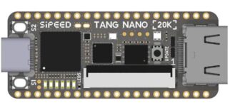
The board is about the size of a stick of gum (22.5 × 54 mm), but it packs a lot:
| Part | What you get |
|---|---|
| FPGA | Gowin GW2AR-18: 20,736 LUT4, 15,552 flip-flops, 48 hardware 18×18 multipliers, 2 PLLs |
| Memory | 828 Kbit block RAM + 8 MB (64 Mbit) SDRAM inside the package |
| I/O | HDMI, 40-pin RGB LCD connector, microSD slot, MAX98357A I2S amplifier, WS2812 LED |
| Debugger | Onboard BL616: USB-JTAG for flashing, plus USB-UART and USB-SPI to the FPGA |
The SDRAM and the audio amp are what make it interesting for me. Almost every project below leans on one or both.
A pattern emerged quickly. In three of the four projects the FPGA is a coprocessor: an ordinary microcontroller (ESP32, RP2040) stays in charge, sends short commands over SPI or a UART, and the FPGA does the heavy work. They even share the same SPI pins, so one wiring harness fits all of them. The fourth project turns that around and puts the CPU inside the FPGA.
1. An Arduino board that is really an FPGA
arduino-tangnano20k is where I started, because I wanted to learn the board from the side I know best. The Tang Nano 20K is a bare FPGA, not a microcontroller, so the package first synthesizes a small RISC-V SoC onto it: a PicoRV32 core plus peripherals. Then it provides an Arduino core that targets that SoC.
The fun part is what “Upload” means here. The IDE compiles your sketch, bakes it into the SoC’s block RAM and rebuilds the FPGA bitstream. Alternatively it writes the sketch to the onboard SPI flash, so the board boots straight into it.
It has grown into a fairly complete core:
Serial,SoftwareSerial, GPIO, PWM,tone(),Servoand the onboard WS2812- I2S audio on the onboard MAX98357A, with optional microphone input
- SPI, I2C (
Wire), the microSD card (SD) and CAN bus viaHardwareCAN - The 8 MB SDRAM as heap for
malloc,newandString, and for code when a sketch outgrows the 64 KB SRAM - Interrupts, timers, DMA, and an INT8 dot-product AI accelerator
- CPU options you pick from the Tools menu: compressed instructions, barrel shifter, hardware multiply/divide, clock speed
That last point is the one I like best. On a normal Arduino board the CPU is fixed; here it is a menu choice. Installing is the usual Boards Manager URL, and it pulls in the RISC-V compiler too.
2. A Faust synthesizer in hardware
TangNanoFaust runs Faust DSP programs on the FPGA and plays them on the board’s I2S amplifier. Faust is a functional language for audio DSP, and normally it compiles to C++. Here it compiles to a custom DSP core I built in the FPGA, with binary32 floating point, all of Faust’s math functions, and delay lines and tables in block RAM or SDRAM.
my.dsp --faust--> bytecode --faust2tang--> DSP core program --SPI/UART/USB--> Tang Nano 20K --I2S--> audio
The key decision was one generic bitstream for every program. Rebuilding an FPGA image for each new patch would kill the fun, so programs load at runtime instead. You can drive it three ways:
- From a PC over the board’s own USB port:
faust2tang my.dsp --port /dev/ttyUSB1 --load, then--set freq=440 - From an Arduino over SPI or a UART, with parameters discovered at runtime and MIDI through any
Stream - From an ESP32 over WiFi:
faust2tangis header-only C++, so it even runs on the microcontroller, or as a compile server withfaust2tang --serve
The DSP core runs at 48 MHz, which gives 1,000 cycles per sample at 48 kHz. Ten sine voices use less than half of that. There is also an 8-channel TDM output for external DACs and codecs.
Status: verified bit- and cycle-exact in simulation, and on a real board over USB, including listening tests and MIDI. A microcontroller on SPI or UART, and TDM with a real codec, are still to be tested on hardware.
3. An HDMI graphics card for microcontrollers
TangNanoGPU turns the board into a graphics card for my TinyGPU library. The microcontroller keeps calling the same drawing API it always did. The calls go over SPI as short commands, and the FPGA draws them into a framebuffer in its SDRAM and streams the picture to HDMI in the background. The MCU needs no framebuffer of its own and pushes no pixels.
- Output: a 320×240 RGB565 framebuffer shown as 640×480@60 on HDMI, or 1:1 on a 4.3″ 480×272 RGB panel. Two framebuffers give tear-free double buffering.
- Drawing in hardware: fills, lines, circles, text, clipping, scrolling, and sprites with colour-key transparency. Sprites are uploaded to SDRAM once and then drawn with tiny
blit()commands. - Drop-in:
SurfaceTangNanois a normal TinyGPU surface, so fonts, 3D wireframes, LVGL and TinyMaterialDesign widgets draw on it unchanged. - Video: H.264 decoded on the MCU by TinyH264 is sent as YUV macroblocks, and only the macroblocks that changed. The FPGA converts them to RGB.
The numbers from simulation at 64.8 MHz show why this is worth it:
| Operation | Time |
|---|---|
| Full-screen clear | 0.72 ms |
| 320-pixel line | 87 µs |
| Filled circle, r = 100 | 385 µs |
| 24×24 sprite blit | 39 µs |
The link is the real limit. A raw full frame (153.6 KB) takes about 38 ms over plain SPI and about 8 ms over quad SPI, which is exactly why the design sends commands instead of pixels.
The one I’m proudest of is the testing. The FPGA uses TinyGPU’s own line, circle and clipping algorithms, and a golden-model test compares the RTL output against TinyGPU’s software renderer pixel by pixel. The gateware is built entirely with the open-source flow (Yosys, nextpnr-himbaechel, Apicula). Status: simulation and timing pass, and on a real board the clocks, HDMI timing and SDRAM start up cleanly. The full picture on real hardware is the next milestone.
4. Neural text-to-speech, with the vocoder in hardware
This is the most ambitious of the four. TinyTTS is my proof of concept of neural text-to-speech running entirely on a microcontroller: a small VITS-style model with 1.6M parameters. It works, but it is too slow, by a factor of about 20 on the fastest ESP32. An ESP32-S3 needs about 34 s to produce 1.5 s of speech.
The culprit is the vocoder. It needs about 440 million multiply-accumulates per second of audio, roughly 90% of the whole model, and the flow is most of the rest. No microcontroller CPU does that in real time.
TangNanoVocoder moves exactly that heavy part into the FPGA:
[embedded content: TinyTTS split across MCU and FPGA]
The ESP32 keeps the light front end and sends only the latent, which is a few KB/s, so plain SPI or a UART is plenty. The FPGA runs flow and vocoder end to end and plays the audio itself. On the board it measures 0.91 × real time: 4.05 s of speech in 3.68 s. The output is bit-exact with my fixed-point C++ model, which matches TinyTTS in float at 39.7 dB spectral SNR.
Two lessons shaped the design:
- Keep the CPU out of the inner loop. My first try used the INT8 accelerator from the Arduino core, driven by the soft CPU. In the fully optimized run, the accelerator was busy for only 81 s out of 34 minutes. The fix was a hardware scheduler that runs the model as a program of op descriptors, fed by its own DMA from SDRAM.
- The latent has to be 16 bit. An 8-bit latent costs 22 dB at the vocoder’s output.
The FPGA loads the 1.6 MB model image from its own flash at power-up, so the microcontroller only sends sentences. While one sentence plays, the FPGA computes the next. Status: the split has run end to end from a PC against the board, but not on an ESP32 yet. Next I want to move the rest of the front end into the FPGA too, so that even an RP2040 can drive it.
What I learned
- Coprocessor beats soft CPU for heavy work. A RISC-V core in the FPGA is great for Arduino-style control, but for DSP, graphics and neural nets a dedicated engine with its own DMA wins by a wide margin.
- The 8 MB SDRAM is the secret weapon. Framebuffers, sprites, delay lines and a 1.6 MB neural model all live there. Without it, none of these projects would fit.
- Test against a golden model. Every project compares the gateware with a software reference: bit-exact for Faust and the vocoder, pixel-exact for the GPU. On an FPGA, that is what makes debugging bearable.
- Both toolchains work. The GPU and the Arduino core use the open-source flow (Yosys, nextpnr, Apicula, openFPGALoader). TangNanoFaust is built with the free Education edition of Gowin EDA.
- Load programs, don’t rebuild bitstreams. Faust patches and the vocoder model are data loaded at runtime. Iterating stays fast, and the microcontroller only has to send a few bytes.
All four projects are open source and come as Arduino libraries:
- arduino-tangnano20k: Arduino core with a RISC-V SoC
- TangNanoFaust: Faust DSP on the FPGA
- TangNanoGPU: HDMI graphics card for TinyGPU
- TangNanoVocoder: neural TTS vocoder
Not bad for a board you can lose in a drawer. If you have one lying around, I’d love to hear what you build with it.
Board specs: Sipeed Tang Nano 20K wiki

0 Comments