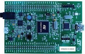
I started to explore the STM32F411 Discovery Kit which comes with the following features:
- STM32F411VE Arm®(a)-based microcontroller featuring 512 Kbytes of Flash memoryand 128 Kbytes of RAM
- A (blue) user push-button
- ST MEMS 3-axis digital gyroscope (L3GD20 or I3G4250D)
- ST MEMS 3D digital linear accelerometer and magnetic sensor (LSM303DLHC or LSM303AGR)
- Four user LEDs: orange, green, red and blue
- ST MEMS digital microphone (MP45DT02 or IMP34DT05)
- Audio DAC with integrated class-D speaker driver (CS43L22)
- USB OTG FS
Getting Started
You need to install STMDuino and the STM Cube Programmer.
Before starting to write some sketches, I suggest that you read the stm32 Wiki.
Some Major Differences to other Arduino Boards
Unlike other Arduino boards, you need to have a USB ST Link connection for programming and plug in a Mini USB cable the the User USB port to get the output from Serial. In the Tools menu select Upload Method: SM32 Cube Programmer (SWD). No port needs to be available to upload a new Arduino Sketch.
Pin Numbering
The STM32 have different pin ports which are identified with a letter. Each port has 16 pins. The Arduino API expects pin numbers of the form ‘P’+PinPort+Pin Number: e.g PA1, PD12 are valid Pin Numbers.
Fortunately this corresponds to the numbers that are printed on the board!
Do not mix up the pin numbers with the pin names which are e.g. PA_0, PB_2. The pin names are stored in the PinName digitalPin[] array and the value of the pin number is just the index to this array.
Missing Board Part Number: “Generic F411 VETx”
As stated above, this board is using the STM32F411VE micro-controller, but unfortunately this is not available in the “Board Part Number” selection list in Arduino. I tried other STM32F411 board numbers and quite a few things were working, but not all because many pins were just not available.
The way to resolve this is to extend the missing board definition. Here are the relevant steps:
- Find the MCU folder “F411V(C-E)T”
- Add the default linker script ldscript.ld: I was just copying the one from the F411R(C-E)T folder. If this is missing you get a linker error.
- Generic System Clock configuration generic_clock.c: I was just copying the one from the F411R(C-E)T folder. But first save the original #ifdef of the original file and adjust it after the copy. If you use the original implementation you get a compile warning and the Serial output will not work.
- Declare the variant: Add the content of board_entry.txt to boards.txt
- An issue with the Arduino IDE 2.x prevents the board to appears in the menu. Follow this workaround to get it working
If you restart Arduino you should be able to select the Board Part Number: “Generic F411 VETx”
Testing with some simple Arduino Sketches
Serial Output
First we test if the Serial output is working. Make sure that you selected
- USART support: Enabled (Generic Serial)
- USB support: CDC (Generic Serial Supersede USART)
The Serial port only gets available after uploading the Sketch.
void setup() {
Serial.begin(9200);
}

void loop() {
Serial.println("test");
delay(1000);
}
Perfect: I can see the expected output!
The User Button
The sketch for accessing the User Button is straight forward since we only need to know the pin number:
#define USER_BUTTON PA0

void setup() {
Serial.begin(9600);
pinMode(USER_BUTTON, INPUT);
}

void loop() {
bool active = digitalRead(USER_BUTTON);
Serial.println(active);
delay(1000);
}
I am getting 0 when the blue button is not pressed and 1 when it is pressed!
I2C
So let’s try something more complicated and let’s try to access the accelerometer & gyroscope. I installed the Arduino library and did not get any output. So let’s try to scan the I2C ports with the Wire / I2C Scanner sketch – but still no success. After checking the pinout for the board I came up with the following solution
// Setup CS pin
pinMode(PE3, OUTPUT);
digitalWrite(PE3, HIGH);

// Setup I2C pins
Serial.begin(9600);
Wire.setSDA(PB9);
Wire.setSCL(PB6);

Wire.begin();
Now I am getting:
Scanning...
I2C device found at address 0x19
I2C device found at address 0x1E
done
LEDs
This turned out the most difficult thing when I started, because I did not have the right board definition savailable yet and the necessary pins were not available with any other STM32F411 board. But with the correct board setting this is working as expected:
#define LED_GREEN PD12
#define LED_BLUE PD15
#define LED_RED PD14
#define LED_ORANGE PD13

void led_toggle() {
static bool active=true;
Serial.print(active);
digitalWrite(LED_GREEN, active);
digitalWrite(LED_ORANGE, active);
digitalWrite(LED_RED, active);
digitalWrite(LED_BLUE, active);
active = ! active;
}

void setup() {
Serial.begin(9600);
pinMode(LED_GREEN, OUTPUT);
pinMode(LED_ORANGE, OUTPUT);
pinMode(LED_RED, OUTPUT);
pinMode(LED_BLUE, OUTPUT);
}

void loop() {
led_toggle();
delay(1000);
}
Cool: All 4 color LEDs are blinking


0 Comments